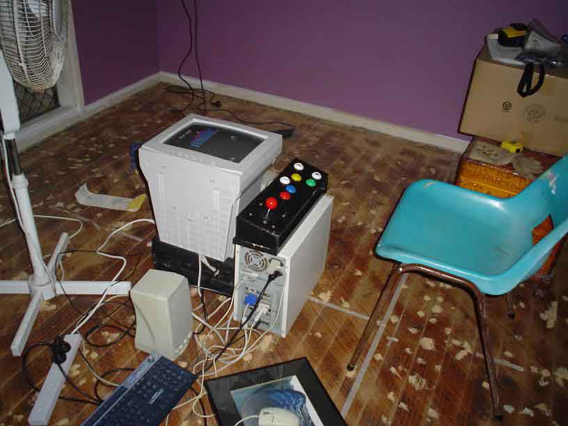
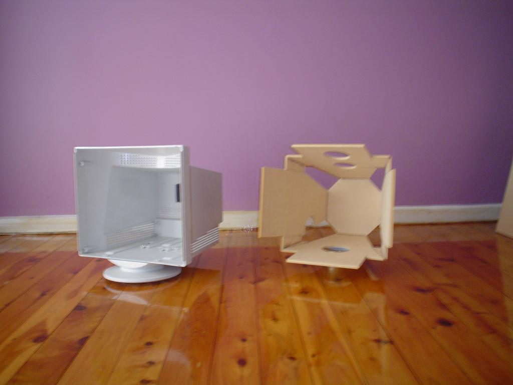
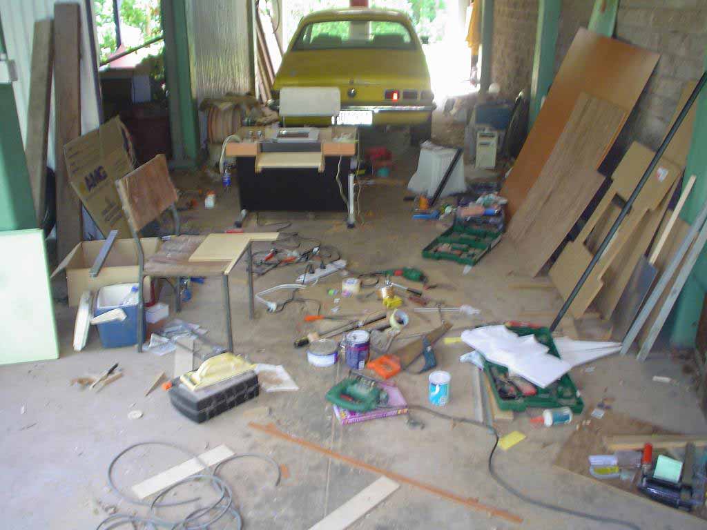
THE UBIQUITOUS 'BEFORE' SHOT
Also happens to be a 'before' shot for the floor. Which I finished before I commenced work on the cabinet.
FUN FOR ALL THE FAMILY!
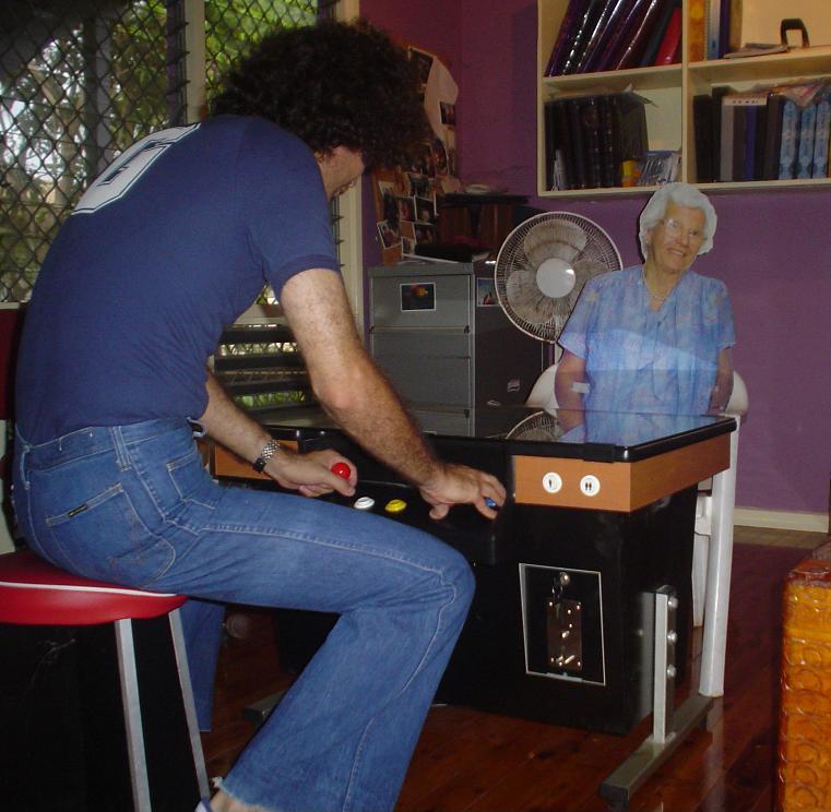
The equally ubiquitous 'after' shot, featuring
Cardboard cut-out Nan.
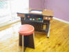
DON'T FORGET THE YOUNG UNS!
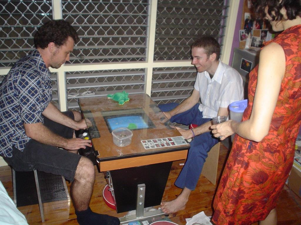
Berserkatron and Snaps play 1942 on the cab. In much need of a dusting after some renovations...
29th Feb, 2004
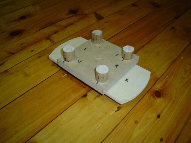
Making a start
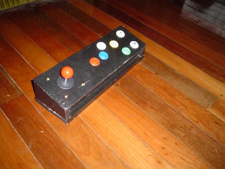
I built a rough console the night I received my parts from Ozstick. This was just so I could evaluate how I would place the buttons and sticks. I had a glitch with the keyboard emulator (an Ipac) at one stage so I tested it in notepad as Ultimarc suggested on their site. Found the fault straight away- it was a shorted wire. I'm very happy with the Ipac.
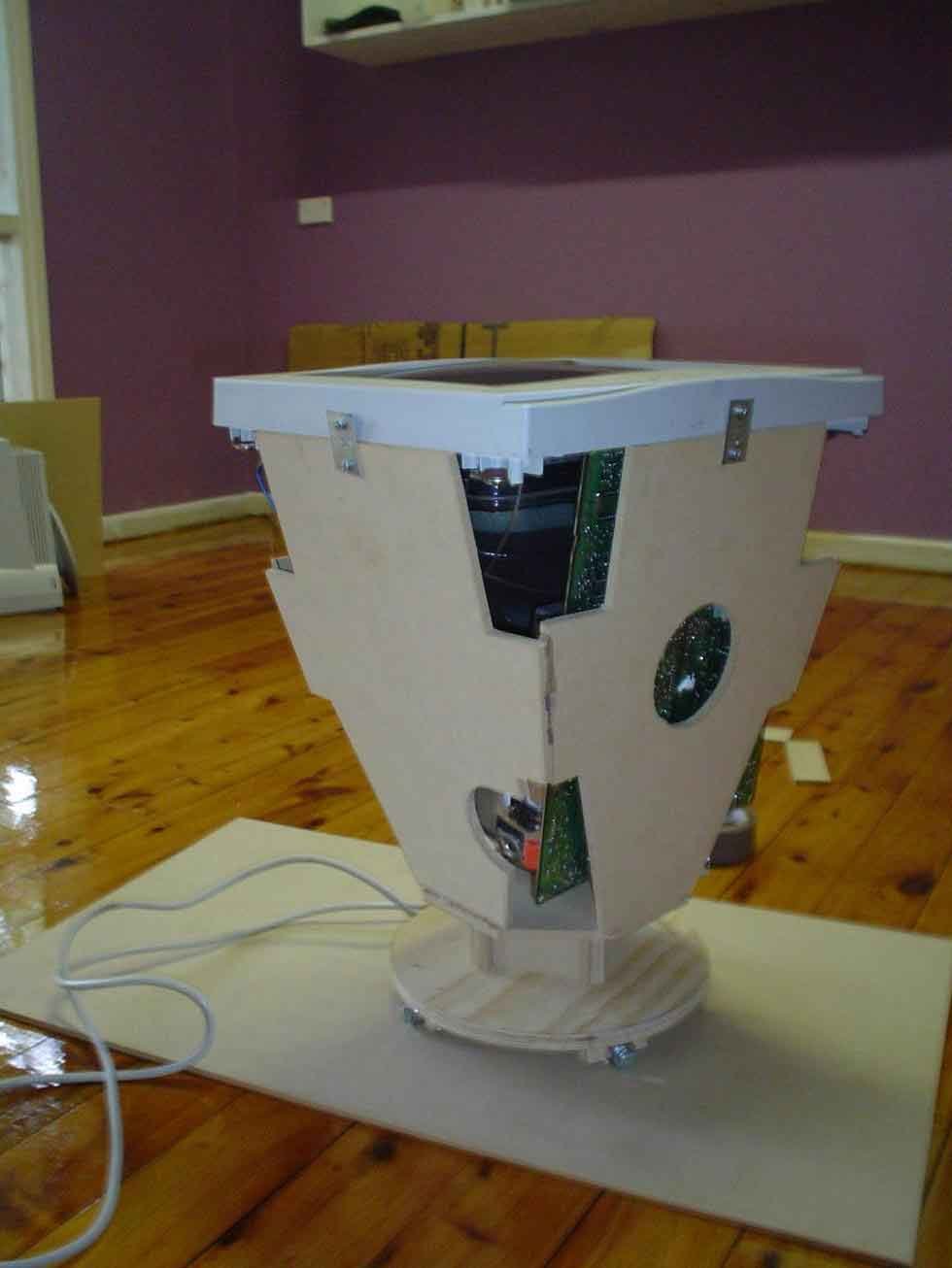
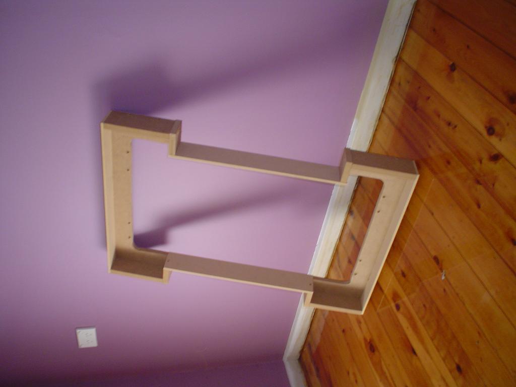
20th March
Let's twist again
In order to
make
the cabinet as close to the standard size as possible, I had to
build a
slimmed down housing for the (new!) monitor. I used 6mm MDF for
this. I
guess that's the end of the warranty...The housing was more of a
sculpture than anything since I knew I would have to carve away
the
bits that didn't allow for rotation. Here you see the general
shape of
it. Once finished I could then offer up the two kick panels up
to it to
see what width the monitor would allow. In the end I only had to
make
the cabinet 34mm wider. Not wide enough to notice, but wide
enough for
me to nickname it 'fatboy'. You can see the turntable for
the
monitor to rotate on. I used 4 x 608 ball races, about the
cheapest I
could find to fit on my 10mm coachscrew axles. You can also see
how
literally I take the expression 'cutting corners'!
Update 2021. The
monitor (a 15" CRT) is starting to play up a little. The way it
behaves makes me think it is a failing capacitor somewhere since
after a few minutes it comes good. I have a spare NIB 15" CRT,
but a different brand. Because of the way I made a custom
fitting housing for it, I know it will be a lot of mucking
around fitting a different monitor in there. I know at least two
CRT gurus local to me. Once we have finished building my
workshop, you can bet I'll be picking their brains and repairing
the original! Still, It's 17 years old now, and has moved
interstate and to four different houses.
21st March
A fitting method
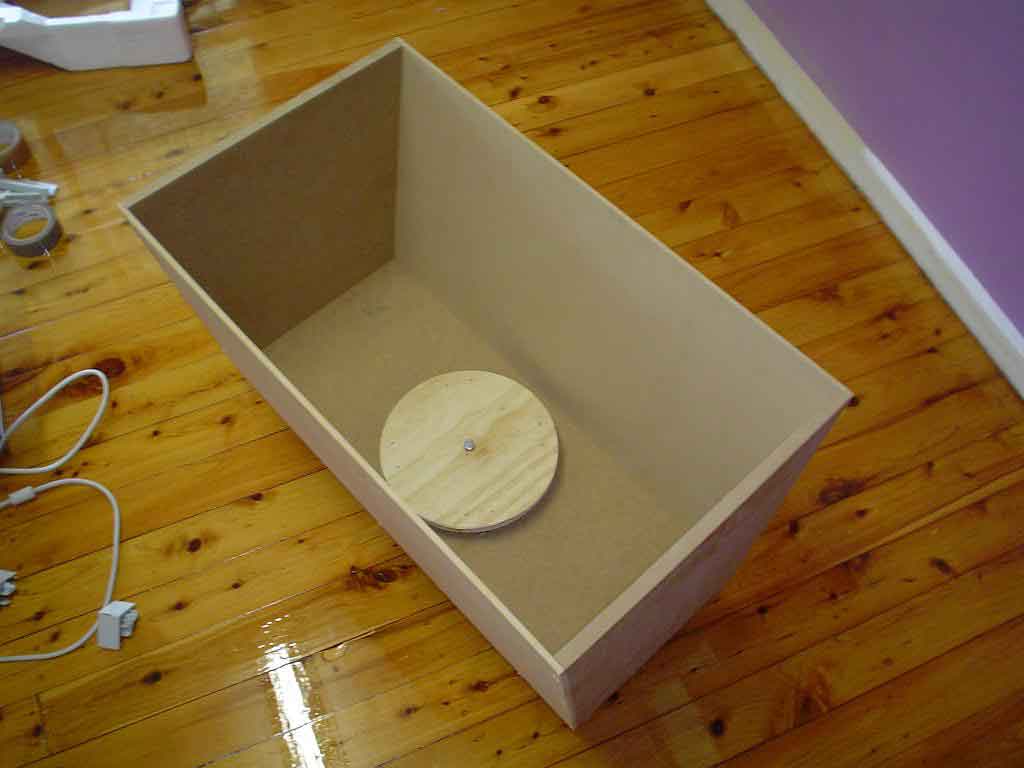
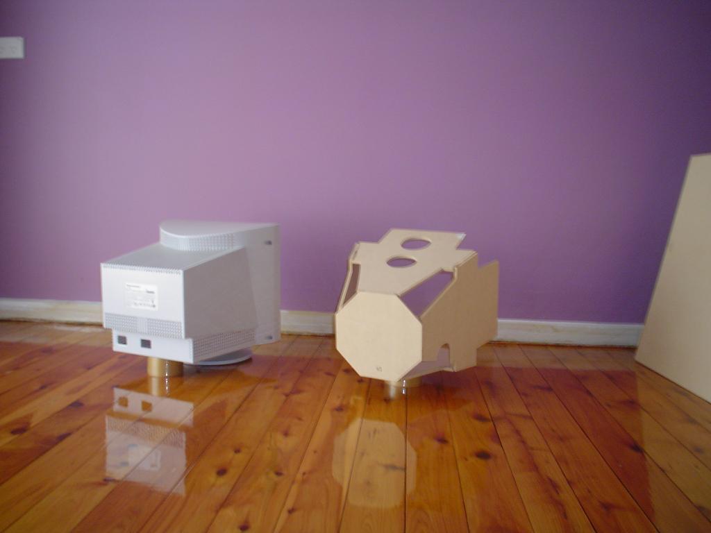
After determining the width I thought I needed, I made the main body of the cabinet. Sides and bottom from 16mm and the kick panels from 6mm to allow as much room for rotation as possible as well as keeping weight down a little. Then I could see if it looked like the monitor would rotate or not. I built the whole thing with the measurements from the site mentioned earlier. I'm the type of guy who 'designs on the wood', a technique that was good enough to build world speed record setting planes in the golden age of flying. And so a print-out of the cab measurements were all I used. This means that I had to think ahead as I went which was a good exercise in itself. Only made a few mistakes...
25th-27th March
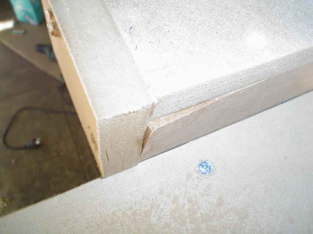
Lookin' good
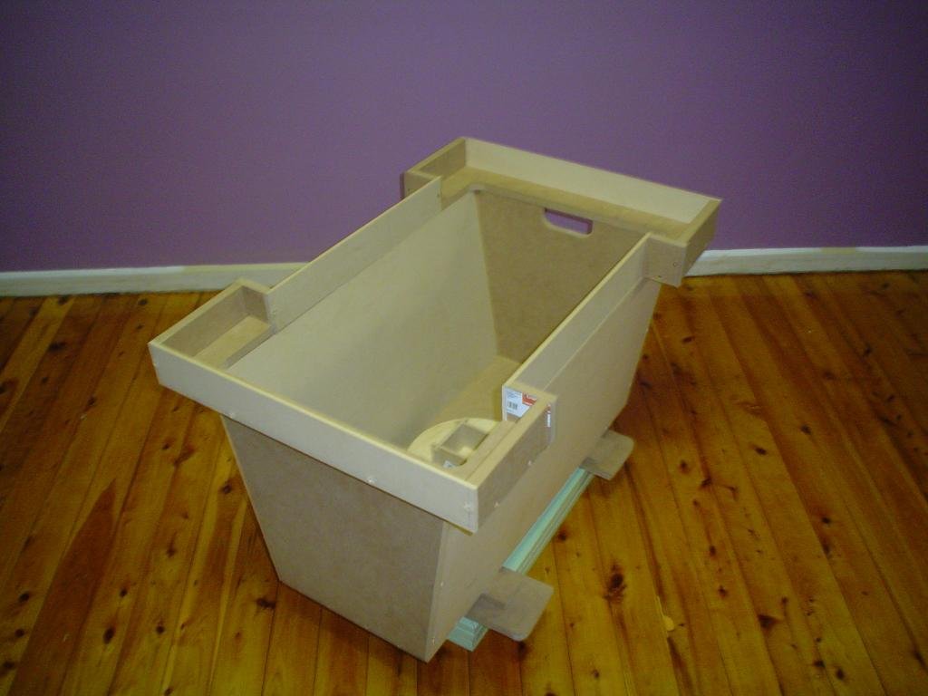
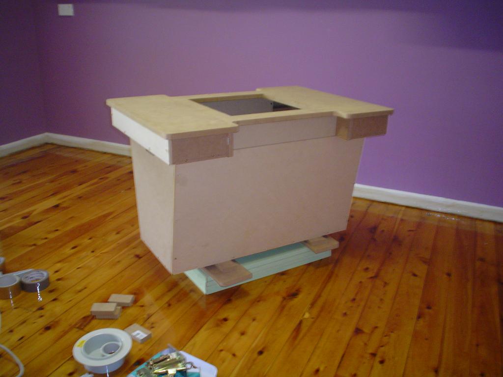
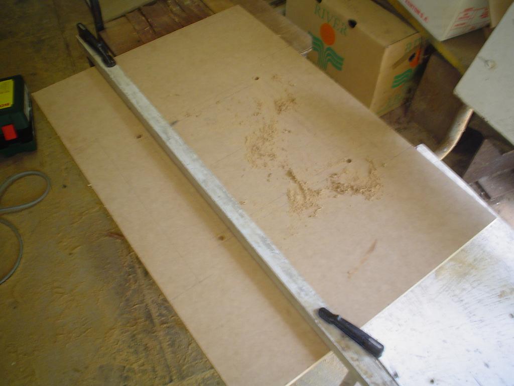
As you can see I made progress fairly quickly bearing in mind that I wouldn't normally end up finishing this sort of project at all! here you can see more clearly how I made the upper part of the cabinet. The 'base' of it is 16mm and then a mix of 6 & 16mm for the edges. This was to facilitate screwing the thin bits to the thick bits. The last pic shows my method of cutting straight with a jig-saw when you don't want to spend money on a circular saw you may rarely use. Angle aluminium is spaced about 30mm in from the line (for my jig-saw anyway). Rather slow to set up but for the odd project like this quite useful. Hey, I just gave you a cabinet-making tip!

Evidence that as a cabinet-maker, I make a good electrician...My mastery of hiding ugly bits under a thin veneer of pretty bits is quite handy. Body filler covers a multitude of sins. To be fair on myself, most of the filler was used to cover screws.
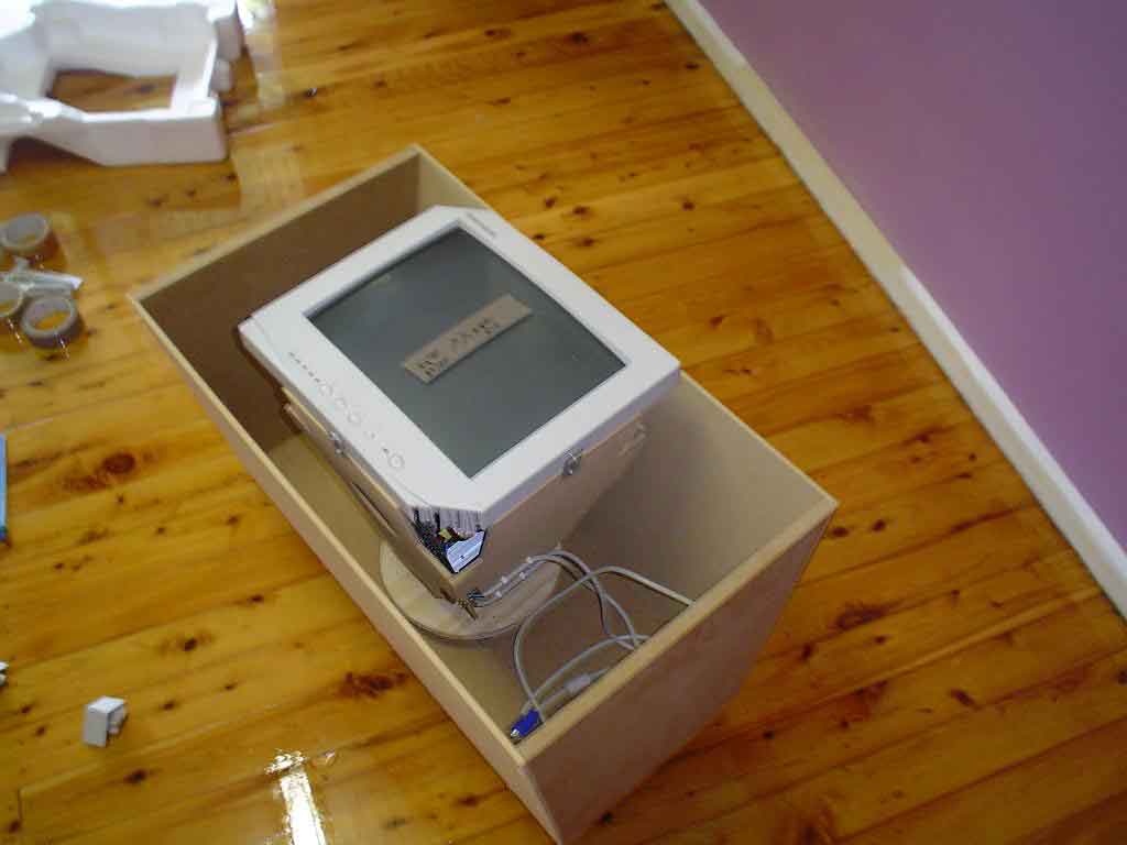
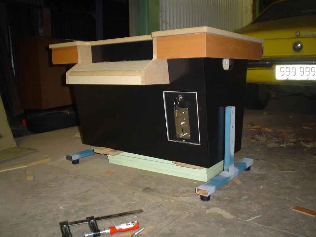
28th March
It's upside down, Miss Jane.
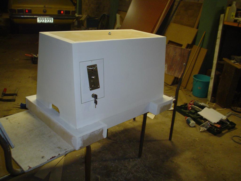
Another tip I can give on cabinet-making is to use an MDF primer if you're using MDF. In Australia White Knight paints used to make it. It's really thick, so you only need one coat to seal the surface. Unfortunately they don't seem to make it anymore. Use an ultra-fine foam roller to apply. This is much neater than trying to spray it and the effect when finished is a very subtle texture- much like laminex which I would have used if it weren't so expensive. At this time I also fitted up the parts for the coin door. It has an aluminium rim on the cabinet to make it nice and neat. This was lucky because I found that the coin mechanism really has to be vertical to work. So once I made the door vertical it became quite inset into the cabinet which looks nice. Note that is not inset yet in this picture.
31st March- 4th April
Console-idation
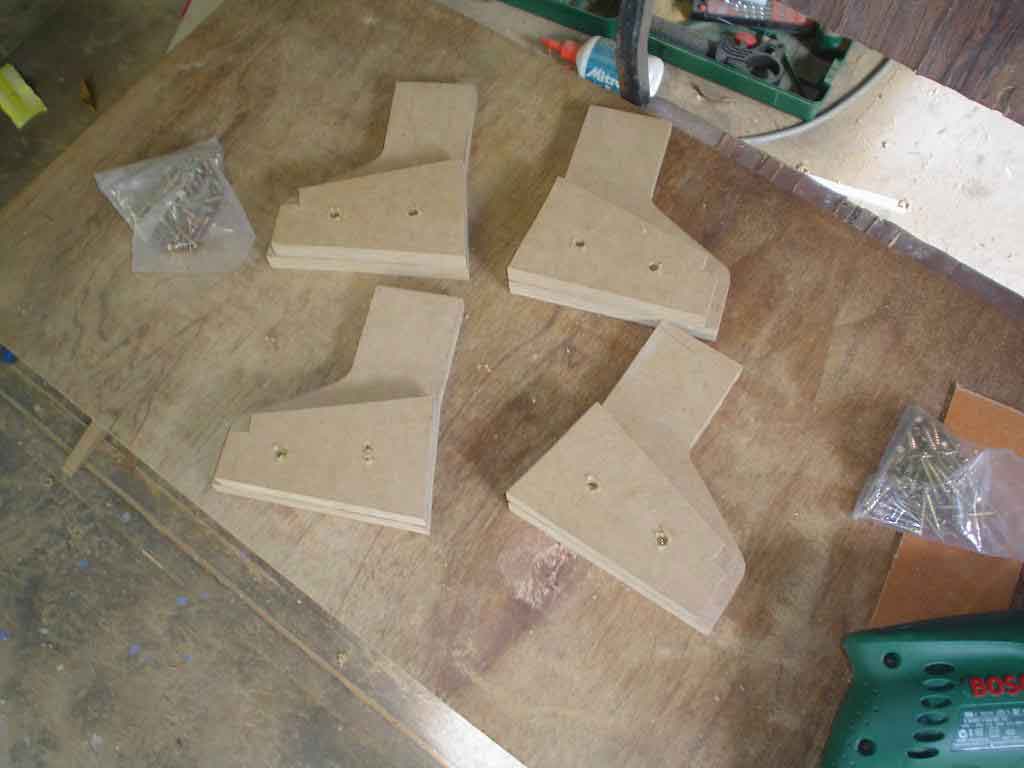
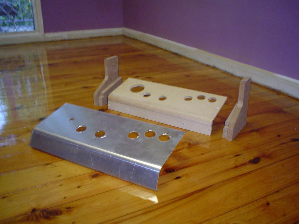
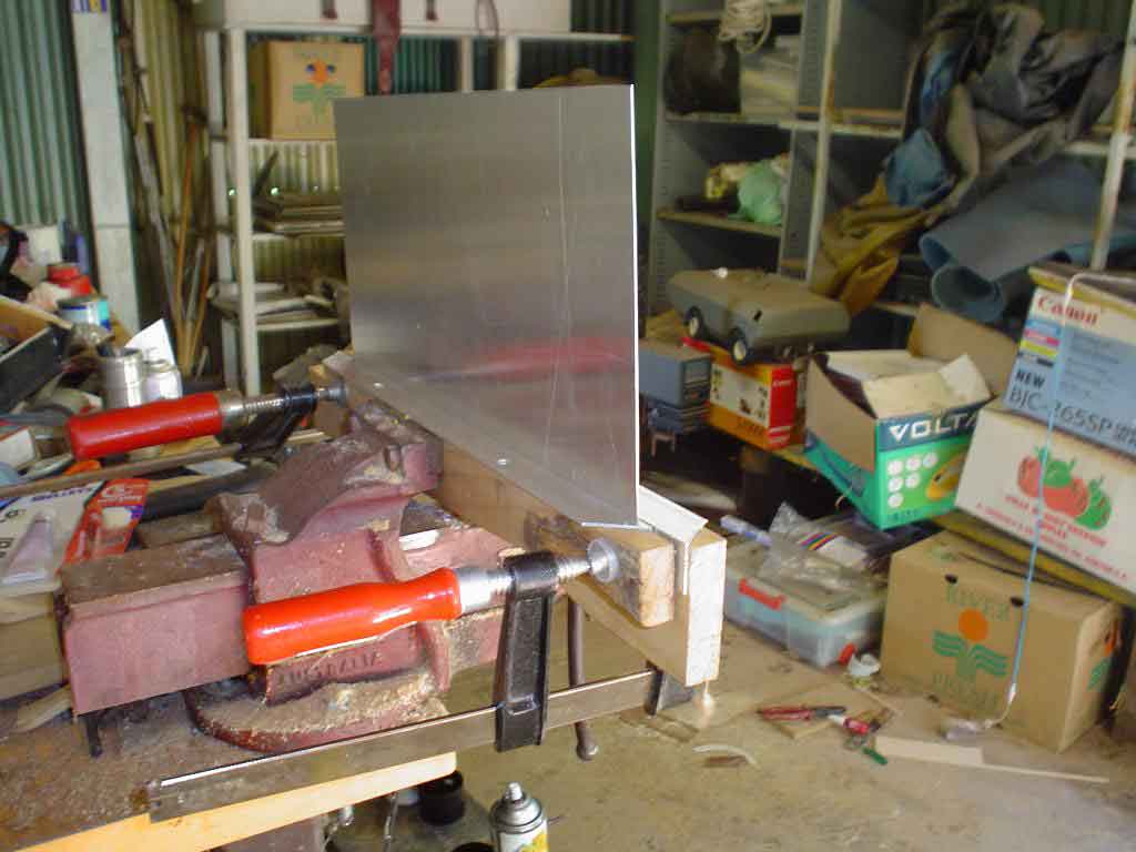
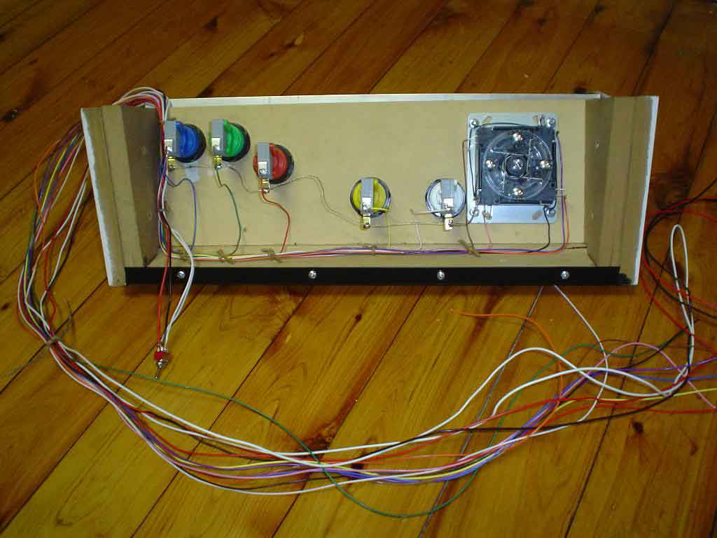
While I was working on the cabinet I was also working on the consoles, which took a bit of doing. I assembled the console without the aluminium first. The bottom of the aluminium has a lip. Here you see the method I use to bend the aluminium neatly. I had a couple of pieces cut for me at a metal shop. Always clamp the shortest part of the bend, in this case the lip. Then bend by pushing it over with a straight piece of wood. when it's bent as far as you can go (and assuming you want a 90 degree bend) and with the piece of wood as a barrier, you can tap it with a hammer until it's really flat. On my console, once I had a lip on the plate, I screwed it onto the MDF and then bent it over and clamped it in place. Then I drilled all the necessary holes. Not perfect, since the ali will spring back about half way if I take all the buttons off. A little bit of heat from a primus on the radius would fix that I guess. Note the difference in size of the joystick holes in the MDF and ali. This is to trap the dust cover between the two. Joystick screws are also hidden under the ali.Once the holes are drilled I then covered the aluminium in vinyl contact. This was why I used metal in the first place. I knew if I just painted the console it would wear off very quickly. If I covered the MDF with contact it wouldn't stick very well and it would trap a whole heap of dust underneath. As it was, it was very hard to keep the ali clean while covering it but it was worth it. Wiping with a clean cloth and meths helped.
in the the last pic you can see how I wired up the controls. Soldered. I later built an upright cab and I just bought a JAMMA harness from ebay for that. You get all the wires and connectors, and more options. note the on-on toggle switch for the monitor motor. I used slightly thicker wire for the toggle than the 25 core data cable I used for the controls since I anticipated up to one amp coursing through it. Fwoar!
I rather like Defender so the
configuration
of the buttons is Defender style. I wasn't going to have any
button mashing fighting
games on my machine (except for games like robocop, simpsons and
asterix which use only two buttons) so if it weren't for Defender
I
would probably only have had three buttons. My version of Defender
doesn't have cocktail mode so I only put three buttons on the
'player
two' side. (2021 update: I play Defender so infrequently that I
kinda wish I only put 3 buttons in)
31st March
Look familiar now?
Coming along quite nicely. You will start to see
more
pics of my grotty work-space instead of the clean new floor
upstairs.
Aussies and Kiwis may recognise the car as a 1972 Holden LJ
Torana.
I've had it for about twelve years. Rebuilt the motor once (186ci.
3 litres in metric). Unregistered
for a while now, but I can't bear to get rid of it. Nothing you
can't
fix on these old beasts (",) . Update 2021: I sold the car for
$500 a while back to just get it out of the way. But right now
Australia is going through a 'Bogan Renaissance' and I could
probably get 2-4 grand for it easy. Oh well.
Back to the cabinet- Also got the legs
back from the metal shop. I don't have a welder otherwise I would
have
done it. They did a better job than I would have though...Using
rubber
door-stoppers for feet.
8th April- 15th April
Jammin' it all in.

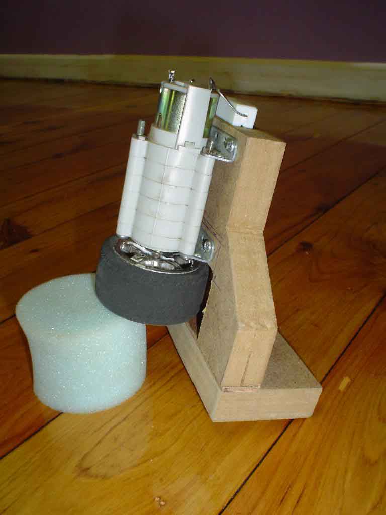

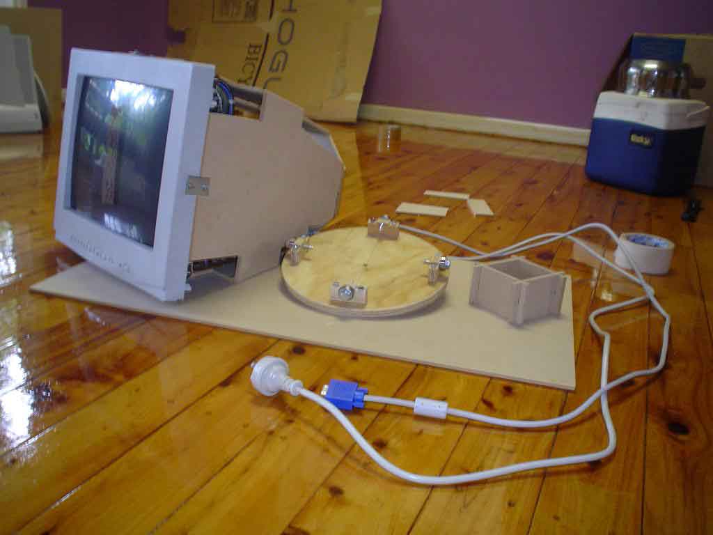
Left pic are the micro-switches. Double stacked, bottom is 240v to switch monitor off while rotating (it has just enough time to degauss in the 3 seconds it's off). I've zapped myself more than once while adjusting! Top set stops motor. 2mm increments drawn on the ali for adjustment. Middle pic is the motor. This is a Tamiya planetary gearbox set. I was going to use an electric screwdriver but then I remembered I had this kicking around somewhere. Bought it over ten years ago. They cost about $27 now- more than the screwdrivers! If you think overclocking a 400mhz CPU to 600mhz is risky then how about a 3v motor running on 15v! You'll notice the resistor on the top- just takes the edge off the power. I have a wheel from a 1/12 model car as the drive-wheel. Fits perfectly, just had to cut a slot for the drive pin. Right pic shows the general layout of the switches. Coin mechanism and switch apparent here.
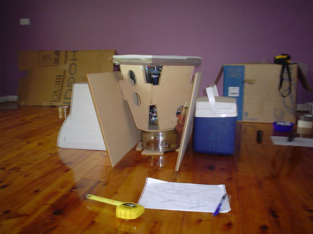
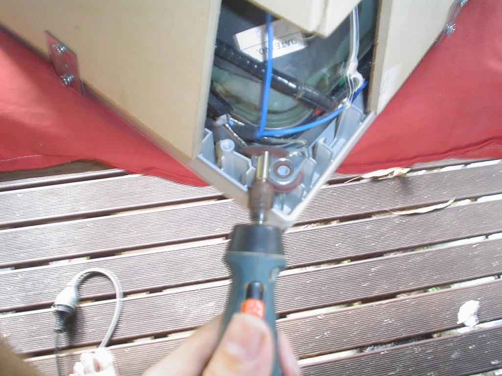
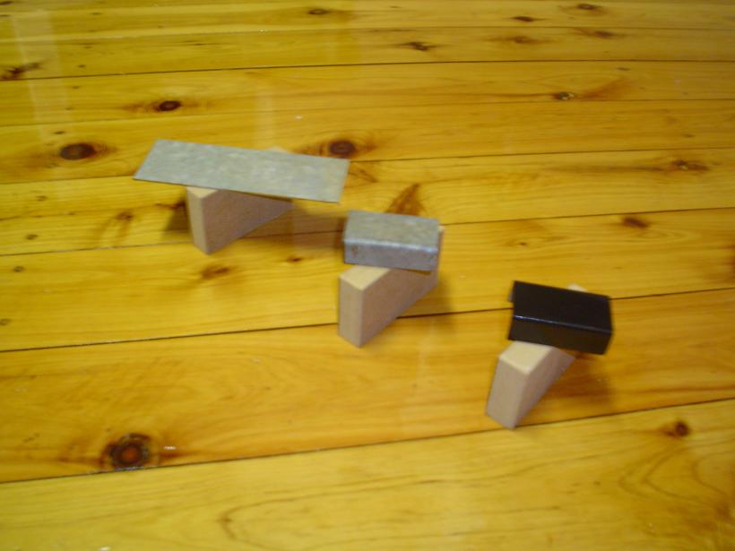
First pic is the final design for the spacer that sits between monitor and turn-table. my home-made case meant that the monitor didn't sit perpendicular, so I needed to adjust the angle relative to the cabinet top. Did this by cutting the spacers close to the right length and then shimming with bits of cardboard underneath them. A whole heap of builders adhesive holds it altogether.
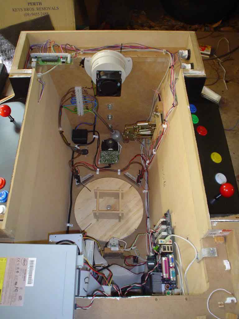
Second pic shows inside. At the top left is the Ipac, next to it is a cooling fan which vents hot air through one of the carry handles. A few PVC plumbing fittings mounts it to allow room to use the handle for it's intended purpose (although i found afterwards that they are practically useless as handles anyway!). Below fan is the right speaker and amp from the speaker set. I imagined that the volume switch would be attached by wires. Instead it is soldered directly to the amp, five tags. So the volume knob extends out the bottom. To the left of the amp is the power supply for it. I also use it for the turntable motor. It's only a 300mA job so if I were to put a voltmeter on the motor when it's running I doubt it would be more than six volts. Note the 240v bus above the power pack. I could have used a powerboard but it would have been very bulky and look hideous. So it's all hardwired. You can see a temporary plug for the monitor, as soon as I had sorted everything the monitor was hard-wired too. To the right of the drive motor is a relay. The 'normally closed' contacts are wired to the 'soft-on' switch for the motherboard. Coil is wired to the15v power pack. This means that as soon as you switch on the power at the wall the contacts open. They are closed long enough though for the motherboard to sense it, imitating the act of pressing the on switch on the case of a pc. Probably there is some sort of BIOS setting that could do the same thing but what do I know? Relays I understand... Besides, if I understood computers better I wouldn't have designed a rotating monitor in the first place!
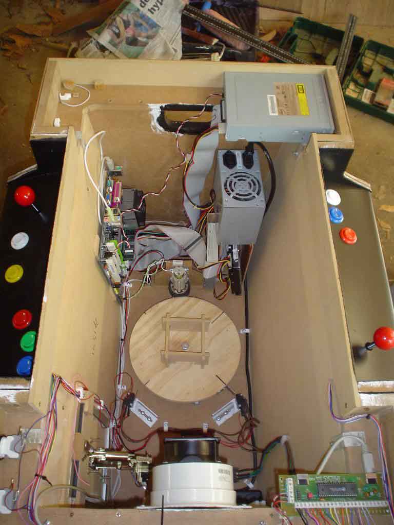
Third pic shows the other view. You can see the general arrangement of the actual computer. Most of the wire I used for the switches, joysticks etc is from 25 core data cable. It is a little thin but at less than a dollar a metre (which is 25 different coloured 1 metre pieces per metre) from Dick Smith Electronics it's good enough! Each wire is multi-strand and it is only being used for signals so it's more than sufficient. (22/05/20: Obviously you won't be buying any wire from Dick Smiths anymore!) I wouldn't recommend single-strand phone wire etc as this is prone to break while you move and adjust things, creating problems you needn't have. Notice that as much as I could I ran the wires in looms. The reasons for looming are two-fold. One- strength in numbers. A wire is much less likely to break when it's physically supported by other wires. Pretty important for the thin stuff I'm using. Two- It's so much easier to follow a wire if there is a problem. I've seen some of the rats-nests in mame cabinets. A nightmare to work out! There is a third reason, although not as important. It just looks a lot nicer. Pity I couldn't loom the ribbon connectors on the computer, would look so much neater. Two intake vents are hole-sawed directly beneath the CPU to let as much fresh air past it as possible. The ribbons partially block these vents but so far the cab has been left on for twelve hours in our tropical heat without any problems.
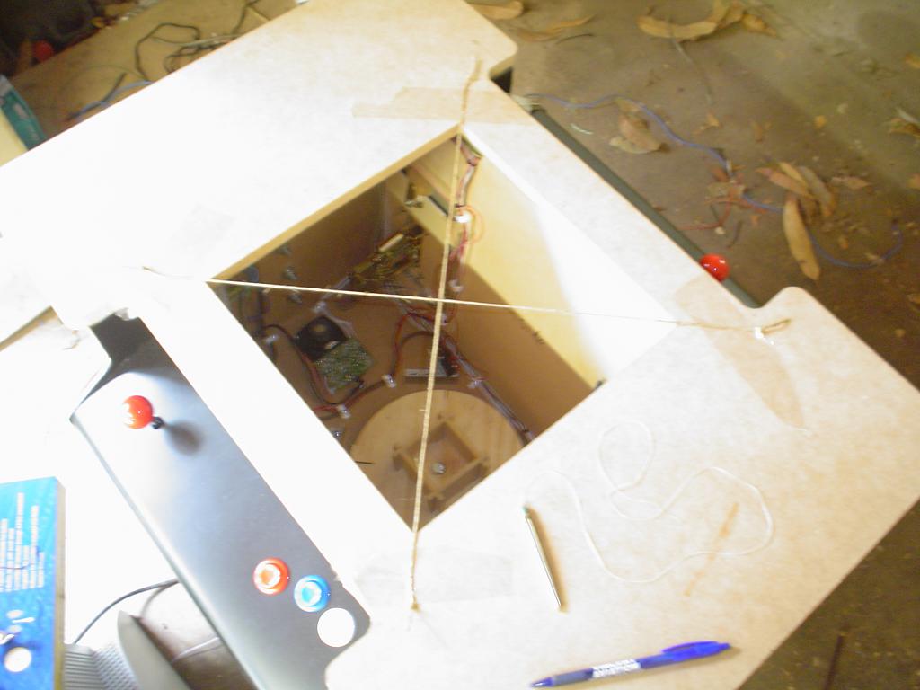
Fourth pic shows method to centre the monitor in relation to the cabinet top. I had an x marked on the monitor.
Miscellaneous debris
The truth will out. I'm a really messy bastard! just how I used to make things growing up. Dad didn't have a work-bench. I have one now, but it's covered in junk! Dad and I still do a lot of our best work on the floor. I made the glass clips from some old zinc plated steel I had lying around. Bent using a similar method to the the ali only using thick steel scrap instead of wood to hit it with the hammer. I bead-blasted the zinc off at a local auto-electricians workshop. Most mechanics and auto-electricians will have a bead blaster if you need one and know a tradesman. I only did this because of the zinc. Paint doesn't stick very well to it, least of all $2 pressure-packs! If I had found some plain steel I would have used that instead.
2nd May
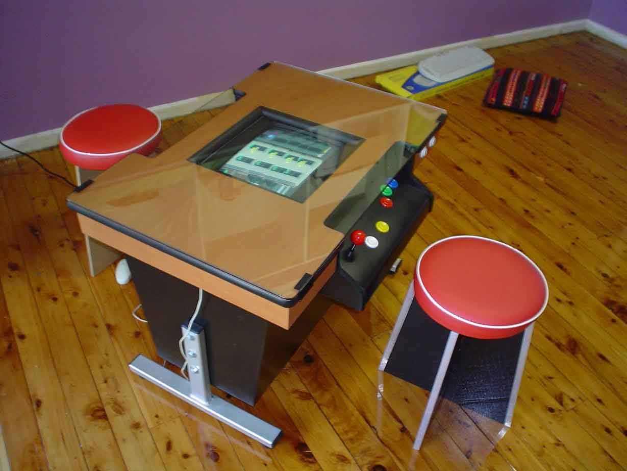
The finished product! Well, when is something like this ever really finished? Basically these are the things I've done to get it to this stage:
I used 3mm pre-finished ply as my 'laminate' as it was about 20% the price of laminex. Of course it's not the same thing. The wood pattern is durable enough on the surface but the edges are prone to tearing. I will run some epoxy on the edges soon to seal it. (19/10/10: and by soon I mean about five years later! At least it's done now). The side parts I cut very accurately to size while the top I cut a few millimetres over and sanded and filed it back to the finished shape. I used builders adhesive to glue it. Easier to move the piece while it's gluing. If I used contact adhesive, Murphy's law would make every piece slightly misaligned...
I slotted the edges with a router to fit 't' moulding on the top and the console ends. Another tip I can give to anyone who, like me has never done this before. Go hard! With my first tentative run I found that the MDF was burning so I cut it on a slower speed and did shallow runs. Wrong! Smoke everywhere. I'm sure I've taken ten years off my life breathing all those fumes. Running it at a higher speed and really pushing it in will cut the material rather than burn it. The 't' moulding itself I initially found hard to procure. Some people hadn't even heard of it. I recommend using it though as it gives a durable edge and makes the machine look like a 'bought' one. On tight inside radii I used 5 minute epoxy on the rib of the 'T' moulding to hold it. The epoxy won't stick to the vinyl as such but will stick very well to the MDF 'locking' the moulding in place. I also cut slits every 5 mm or so on the 'spine' of the T molding twhere there were tight inside radii. And notched the spine every 5mm or so for tight outside radii. Much more flexible that way.
I had my heart set on chroming the legs but the only chroming place in town was gone. Not moved, or closed business- but just gone! There was rubbish all around the workshop, chemicals leaking out of the shed and it smelled like a dead animal was in there too. Hopefully not the proprietor! So I spray painted the legs with cheap pressure packs. A coat of primer followed by two or three coats of aluminium and then a coat of clear. I recommend steering clear of 'chrome' paint as it will turn out looking like it 'wants to be' but isn't quite. Finished off the legs with some plastic closures. The steel for the legs is 50mm x 25mm box. I've seen on someone else's site that they had trouble finding it. I found that Bunnings have that size although I would have to buy 2.4M of it. I found a second hand building supplier who would cut new stock to length. Cost me $17 in material.
The cab itself is painted with gloss black acrylic. Again with a super-fine foam roller. The only drawback of gloss black acrylic is that it never seems to harden the way most other colours do. But since you don't come into contact with the surfaces that much I'm not too worried about it.
I left the glass until last as it was bloody expensive! 6mm cost $126, 5mm only ten bucks or so less. Might as well have six. A tip here is to have a long think about the dimensions you have it cut. I had mine cut exactly the size of the top. This means though that you can see a millimetre or so of wood-grain 'peeping' out from under the bevelled edge of the glass. It might have been better to get it cut to about the size of the top including the 't' moulding. edit 19/04/08: just reading this again i think it was better to have cut the glass the way i did- the t-molding offers more protection for the glass that way.
I bought a cordless keboard and mouse from Coles for only $20! Its not brilliant but it doesn't have to be for this. Only problem is I have to extend the mouse connection since the keyboard and mouse plugs ended up on opposite ends of the cab.
The stool legs are 12mm MDF and the seat bases are 300mm circles cut from leftover 16mm. I was conscious that the project wouldn't really be finished until we had something to sit on. Height is 420mm to the underneath of the base. I had four of them upholstered. The plan is to have two different heights. The stool legs looked a little plain in contrast to the funky upholstery so I painted them gloss black and capped the edges with 15mm ali channel.
The bezel/frame thingo that tidies up the monitor cut-out in the top is made from 19mm quad, which I also used for the front edge of the consoles. The frame bits had maybe four coats of primer and over ten (!) coats of black on it. If I'd have put just one more coat of primer on it, I might have avoided the last five coats of black...
'To do' list
Had a hard time aligning the top when hinging it. It ended up slightly to the left. This is why I haven't attached the other four glass clips. Two of them just won't fit! Will eventually fill in original screw holes with epoxy and redrill.
I must soon make a nice instruction placard to slip under the glass instead of the grotty bit of paper I have sticky taped on top of it. Update: done! here
Must finish the other three stools.
Use a relay on the monitor power. This is so that when the monitor stops rotating it doesn't switch back on until a second or so after it stops moving. That should allow it to just about completely degauss every time. 'Commando' in particular is really effected by this problem. It sometimes gets purple corners. It depends on what sequence I use in rotating. Electric motors tend to spin faster one way than the other so the monitor rotates one way quicker than the other.Most of the time the games are fine though so I won't be hurrying to put the relay in.
This is one of the
cooler things I want to do. I can't see why I can't have the
monitor
rotate automatically upon selection of a game. I'm not a
programmer but
I think it would basically entail a program that senses
which game is
selected and then sending a signal to the parallel port
where I can use
power transistors or mini relays to run the monitor motor.
The signal
only has to be a constant output from either one pin or
another as the
'thinking' is done with micro-switches on the turntable. I
could just
about do this myself with a macro and utilising the
'orientation'
folder. Wouldn't be satisfactory though since it would mean
tabbing to
and fro different lists. The games wouldn't be alphabetical
in one list
either but rather in two lists. Any thoughts? Perhaps the
program could
read the game info screen that appears when you first select
a game... Update 30 March 2021. I am now using Mala, and it
actually has provision for a plug-in for automatic monitor
rotation! I'm actually not going to bother. I'm just happy
it rotates the menu screen. This means a lot less monitor
rotating.
My next intended
step
is to have the joysticks electrically select four or eight
ways. And
you guessed it, once I've sorted that out then why not have
a program
select it according to the game? Probably I'll end up
conceding defeat
there and buy some T-stiks from Ultimarc or Groovy
game gear
or similar. 22/05/20: Well it turns out that Ultimarc came
out with an
electrically selectable 4/8 way Sanwa joystick! There's nt
quite enough
space in my cocktail control panel but I built an upright
and installed
them in that. Using Mala as the front end means they are
automatically
switched according to what game is selected. Brilliant!
BEHOLD! IT'S ALIVE!!
Short movie of the beast in action. About 266k in size.
also now on youtube. looks much worse there but google likes sites that reference each other (",)
BEHOLD! NEW FRONT END!!
04/01/11: I finally took the plunge and tried out a proper front end, to disguise the very window-y look of mame32. Since I didn't want to muck around too much, I downloaded 6 or so flavours and proceeded to try them all until I liked something. And the winner? MaLa! This is bloody brilliant! I spent three nights in a row staying up until 3am or so fiddling with it. Not because it's really hard to set up, but because it has so many features. I'd keep discovering new things to try until the early hours. I started off by thinking I'd just make a vertical menu, since more often than not the monitor ends up in that orientation. Then I realised that actually, in MaLa, there is a setting that automatically switches between a horizontal or vertical menu according to last game played. Bloody brilliant! It also has 'plug in' capabilities to insert different functions. You guessed it, people have made plug ins for MaLa to automatically switch the monitor rotating motor according to game selected. I haven't gone that far yet. I'm still stoked about the rest of the features.
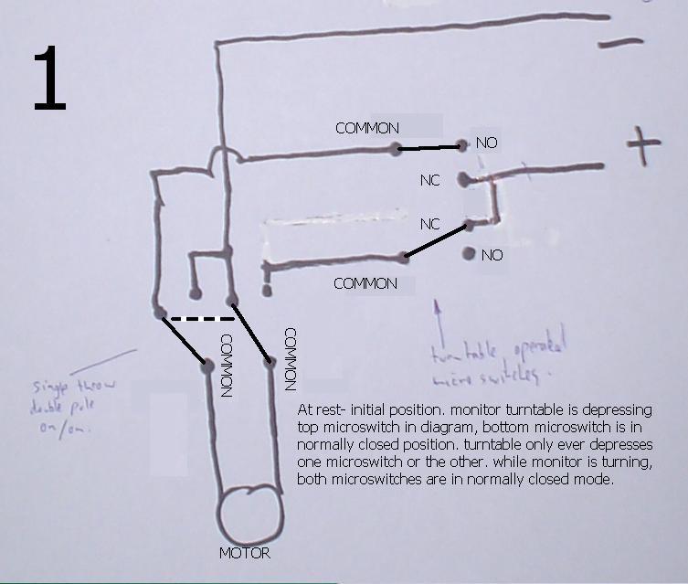
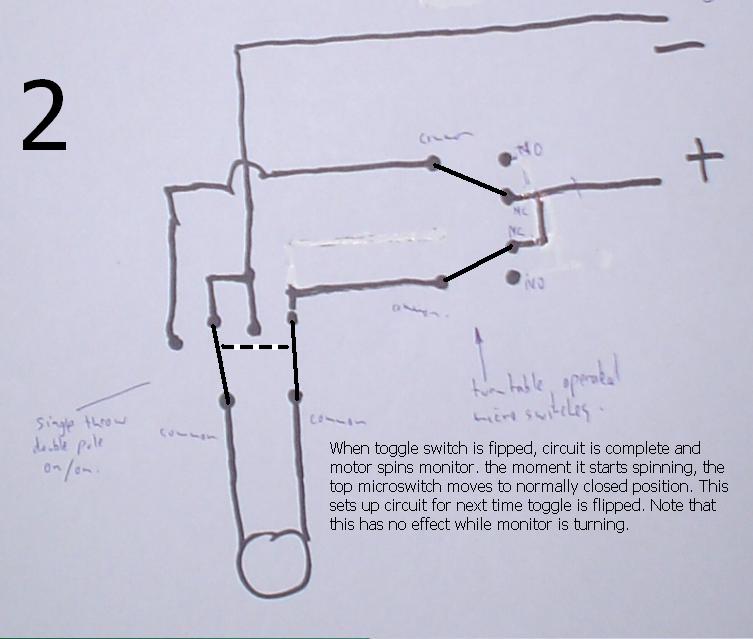
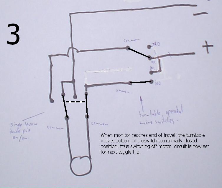
Update: Here are some sketches of the rotating monitor circuits. There are two circuits.One is to automatically stop it turning and the other is to turn off the monitor while rotating thus allowing it to deguass in that time. The degauss circuit is not shown here as it is easy to understand what needs to happen.
 |
story? |
complaints/contact |